
MISCELLANEOUS
M 565 v3
Quad Quantizer
M 565 D
Quantizer
Controller
M 512
Audio Interface
M 544 CP
Utility Module
M 554
Octal Clock Divider
M 595
12 x12
Programmable
Switch/Summer
Matrix System
M 528
Sample and Hold
M 567
Universal Programmer
M 591
Quad Switch Matrix
M 592 Reversible Modulation
Matrix
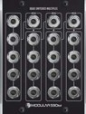
M 594
Multiples
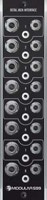
M 599
Jack Interface
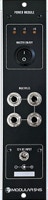
M 545
Power Supply
Kits
M 500
Blank
Front Panels
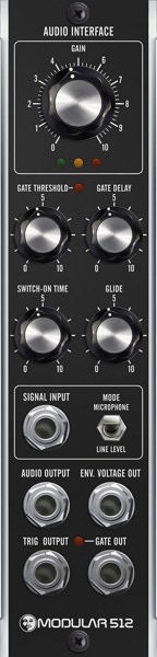
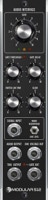
M 512
Audio Interface
Envelope Follower
Trigger/Gate Extractor
Via the M512 AUDIO INTERFACE one can integrate external Audio and different Instruments into his modular system. First it is a preamplifier to raise microphone or line signals to modular level to be used inside the synthesizer system.
· The signal passes the gain control with 3-LED-level indicator
and microphone/line level input switch.
· The audio output provides the amplified input signal.
· The gate/trigger threshold control defines the level from which the
gate/trigger puls is released
· The Switch-on time defines the lengths of the gate pulse,
the gate delay controls the delay of this pulse.
· The glide control “softens” the form of the generated envelope voltage.
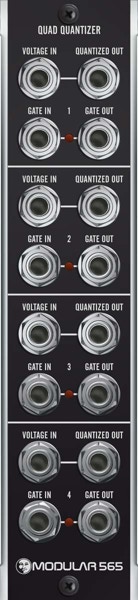
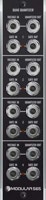
M 565 v3
Quad Quantizer
QUAD QUANTIZER featuring four independent quantizer circuits forces variable control voltages into semitone intervals (1/12 volt) over a bipolar input voltage range of more than twenty octaves (255 semitones).
Gate pulses fed into the “Gate In“- jack trigger the quantizer. An “open“ gate input quantizes, i. e. if no gate jacks are patched. The four gate-ins are passed through, one plugged IN 1 feeds IN 2 to IN 4 as well.
The gate outputs supply a pulse, when- ever the (quantized) output voltage changes. The most recent quantized value remains preserved until the next quantization will occur.
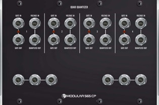
This module is also available as CP-size module (4 units wide).
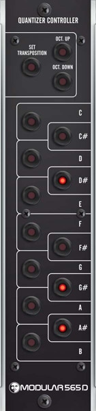
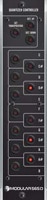
M 565 D
Quantizer Controller
The QUANTIZER CONTROLLER allows to limit the output voltages generated by the M 565 v3 Quad Quantizer to any desired key, chord or note interval. Using the array of 12 keyboard-like arranged LED buttons, notes can be activated or deactivated in any combination. Up to two M 565 D Quantizer Controller modules can be connected to a single M565v3. If only one M565D is connected, all 4 channels are forced to its settings.
If two M 565 D are connected channels 1 and 2 are controlled by the first and channels 3 and 4 by the second. Multiple quantization settings can be stored if a M 567 Universal Programmer is connected to the M 565 v3.
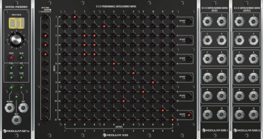
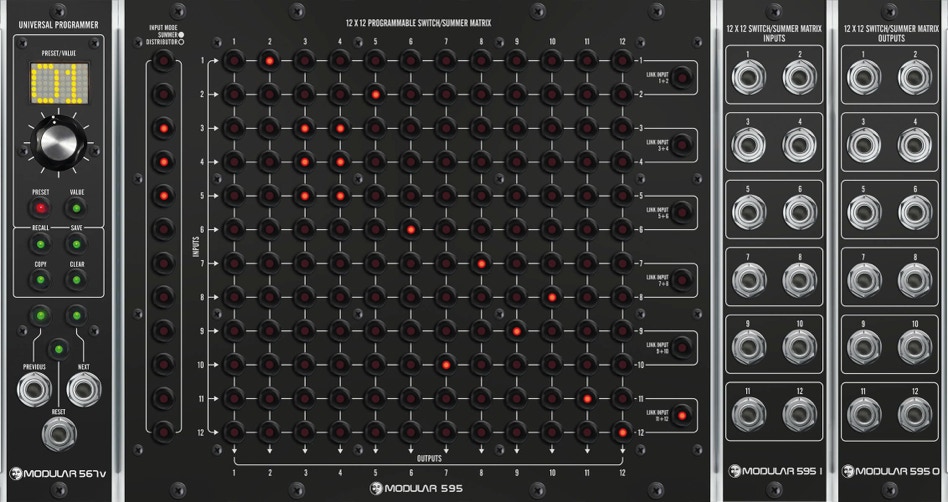
M 595/567 V
12 x12 Programmable Switch/Summer Matrix
The PROGRAMMABLE SWITCH/SUMMER MATRIX is a solution to manage the distribution and/or mixing of 12 by 12 DC-coupled and buffered inputs and outputs, fully analogue with a high precision signal path.
INPUT MODE: Routing/Distribution (off/on) or mixing signals (off/third/twothirds/full)
LINK MODE: Inputs and outputs are paired to handle immediately a combination of e.g. the
CV and GATE outputs of a sequencer or a stereo audio signal.
PROGRAMMER: 99 memory locations with an independant edit buffer.
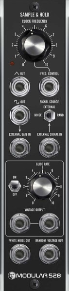
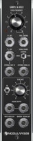
M 528
Sample and Hold
The M 528 module is a sample & hold circuit consisting of the following elements:
· The voltage controlled clock oscillator gates the sample circuit and doubles as a VCLFO with triangular and rectangular waveforms.
· External gate input
· Signal input can be the internal noise source (white noise and random voltage, both with separate output jacks) or an external sample signal.
· Dual voltage output jacks with switchable variable glide (portamento) control.
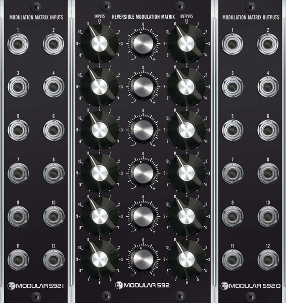
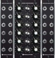
M 592
Reversible Modulation Matrix
The REVERSIBLE MODULATION MATRIX combines six attenuator-units, consisting of three elements each:
· 12 position input selector to choose one of 12 signal inputs
· reversible attenuator, which attenuates or amplifies the input signal in a range from -200 % to +200 %; in zero-position the signal is suppressed completely
· 12 position output selector to chose one of 12 signal outputs
The complete modulation matrix consists of three (or in one special case two) modules – the central active control unit M 592 and the sub-modules M 592i/592o with 12 in- and 12 output-jacks. The inputs are connected via switching jacks: one single modulation source can – without any extra patchcord – routed to several different outputs at once, via independent attenuators.
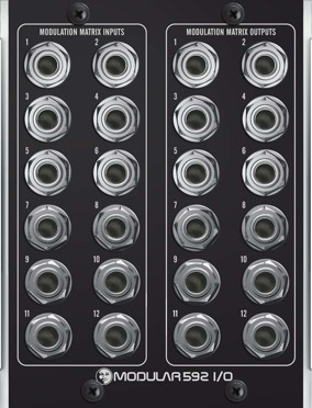
M 592 I/O
An alternative In-/Output Module in the
Moog CP form factor
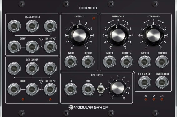
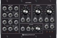
M 544 CP
Utility Module
The M 544 CP UTILITY MODULE incorporates a couple of useful control voltage and logic functions.
· Two attenuators which double as
2-channel mixer and inverter
· Slew limiter
· Gate delay
· 3-input voltage summer/inverter
· 3-input gate summer/inverter
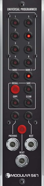
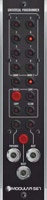
M 567
Universal Programmer
The UNIVERSAL PROGRAMMER MODULE enables the user to save and recall settings from the 568 sequencer, 565D quantizer controller and future modules. The 567 can save 2 x 8 settings in its non volatile memory.
Operation is simple. Via the push buttons the user selects one of 8 memory slots. Two memory banks are selected via the bank buttons. Four push buttons control the memory operations. With the lower “go to” buttons/ jacks one can step through memory positions in either direction, even by trigger pulses from external sources (or from a 568 itself).
This way extremely long trigger sequences could be made possible.
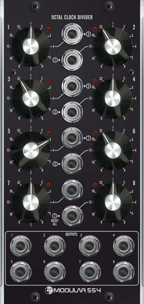
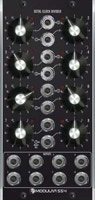
M 554
Octal Clock Divider
The OCTAL CLOCK DIVIDER combines 8 divider circuits in one module.
Each of the dividers offers twelve division factors:
1 · 2 · 3 · 4 · 5 · 6 · 7 · 8 · 10 · 12 · 16 and 32.
The input jacks are normalized to allow complex divider combinations without external patching: Input 1 is daisy chained to input 3, input 3 to 5, input 5 to 7. Output 1 is daisy chained to input 2, output 3 to input 4, output 5 to input 6,
output 7 to input 8.
Input 8 can be configured (jumper on the main circuit board) to serve as master reset input for dividers 1 to 7.
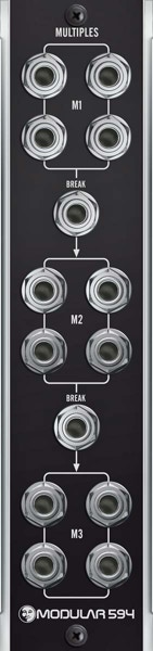
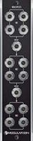
M 594
Multiples
MULTIPLES MODULE with 3 x 4 sets of jacks.
By using the two additional ‘break’-jacks, one can use this module as one, two or three independent four-jack- multiple areas.
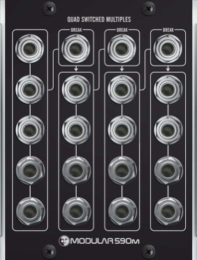
M 590 MCP
Multiples
MULTIPLES MODULE in the Moog CP form factor.
By using the three ‘break’-jacks, one can use this module as one, two, three or four independent
four-jack-multiple areas.
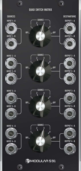
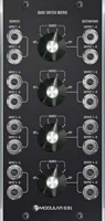
M 591
Quad Switch Matrix
The QUAD SWITCH MATRIX ROUTER is a passive module, where 2 x 4 output jacks (“destinations“) can be routed in pairs to 2 x 4 signal inputs (“sources“) using four 6-way rotary switches with two “off “-positions.
This simple device is intended as a companion module to the M552, but suitable for a multitude of applications, where audio- and control-signals have to be routed fast and with immediate visual feedback. 
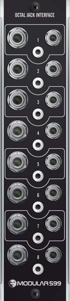
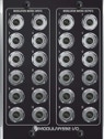
M 599
Jack Interface Module
INTERFACE MODULE with eight sets of jacks:
· 1/4” (6,35 mm)
· Banana
· 1/8” (3,5 mm).
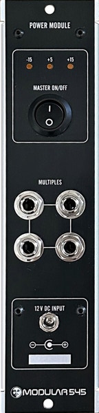
M 545 1A
Power Supply & Distribution Module
The POWER SUPPLY MODULE M 545 1A combines a one unit module with a eight header distribution board,
a four jack multiple, master switch and display leds for the three voltages.
Eight DotCom* style power connectors to feed the attached modules. Via the dedicated connector an extra power distribution board (500PD) not included can be applied to drive more modules.
The three output voltages are
+15 V (1 A) | -15 V (1 A) | +5V (0.6 A)
A 2.5A external multi region power adapter and eight
500-PDotCom cables are included.
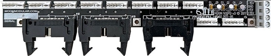
500PD extra power distribution board (included with the M 545 2A version)
*Trademarks are the property of their respective owners
M 545 2A
Power Supply & Distribution Module
The POWER SUPPLY MODULE M 545 2A combines a one unit module with a ten header distribution board,
a four jack multiple, master switch and display leds for the three voltages.
Ten DotCom* style power connectors to feed the attached modules.
Via the included extra power distribution board (500PD) it can drive more modules.
The three output voltages are
+15 V (2 A) | -15 V (2 A) | +5V (1.2 A)
A 5A external multi region power adapter and 16
500-PDotCom cables are included.
M 500
Blank
Faceplates
BLANK FACEPLATES with or without the ’Moonface‘ logo, in one or two unit widths.
Copyright © 2024 Les MoMo Consulting